O Level 2026 Practical Exam Preparation | Complete Arduino Programs with Output
📚 Table of Contents
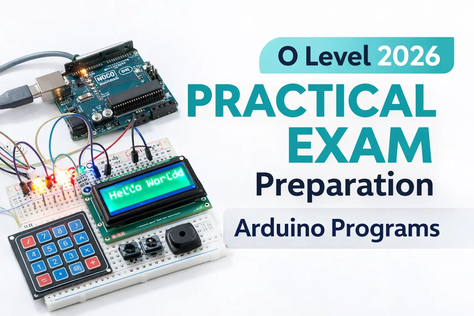
O Level 2026 Practical Exam Preparation Complete Arduino Programs with Output LED | Buzzer | LDR | LCD | Keypad
📌 Quick Summary
Introduction to Arduino Practical Programs This blog provides complete Arduino practical programs with LED, buzzer, LDR, LCD and keypad. These progra...
This article is written for beginners who want to learn and build a career in O Level 2026 Practical Exam Preparation | Complete Arduino Programs with Output.
Introduction to Arduino Practical Programs
This blog provides complete Arduino practical programs with LED, buzzer, LDR, LCD and keypad. These programs are exam-oriented and suitable for diploma, BCA, B.Tech and beginner-level Arduino learners.
1. Blink Default LED with 2 Seconds Delay
This is the most basic Arduino program used to understand digital output control. It helps students learn pinMode(), digitalWrite() and delay() functions, which are commonly asked in O Level practical exams.
void setup() {
  pinMode(LED_BUILTIN, OUTPUT);
}
void loop() {
  digitalWrite(LED_BUILTIN, HIGH);
  delay(2000);
  digitalWrite(LED_BUILTIN, LOW);
  delay(2000);
}
2. Blink LEDs on Pins 10,11,12,13 Alternately
This program demonstrates how to control multiple LEDs using arrays and loops. It improves understanding of sequential execution and is useful for LED-based practical questions.
int leds[] = {10,11,12,13};
void setup(){
  for(int i=0;i<4;i++) pinMode(leds[i], OUTPUT);
}
void loop(){
  for(int i=0;i<4;i++){
    digitalWrite(leds[i], HIGH);
    delay(1000);
    digitalWrite(leds[i], LOW);
  }
}
3. LED Pattern Program
This program creates different LED glow patterns using nested loops. Pattern-based programs are very common in Arduino practical examinations.
int leds[]={10,11,12,13};
void setup(){
  for(int i=0;i<4;i++) pinMode(leds[i],OUTPUT);
}
void loop(){
  for(int i=0;i<4;i++){
    for(int j=0;j<4;j++)
      digitalWrite(leds[j], j==i ? HIGH : LOW);
    delay(1000);
  }
}
4. Buzzer ON/OFF with 1 Second Delay
This program explains how to interface a buzzer with Arduino. It is useful for alarm, alert and notification-based practical applications.
int buzzer = 9;
void setup(){
  pinMode(buzzer, OUTPUT);
}
void loop(){
  digitalWrite(buzzer, HIGH);
  delay(1000);
  digitalWrite(buzzer, LOW);
  delay(1000);
}
5. LED and Buzzer Together
This program shows how to control multiple output devices simultaneously. The buzzer turns ON whenever the LED is ON, demonstrating synchronized output control.
int led=10, buzzer=9;
void setup(){
  pinMode(led,OUTPUT);
  pinMode(buzzer,OUTPUT);
}
void loop(){
  digitalWrite(led,HIGH);
  digitalWrite(buzzer,HIGH);
  delay(1000);
  digitalWrite(led,LOW);
  digitalWrite(buzzer,LOW);
  delay(1000);
}
6. Button and LED Interface
This program explains digital input using a push button. The LED glows only when the button is pressed, which is a fundamental concept in Arduino practical exams.
int button=7, led=10;
void setup(){
  pinMode(button,INPUT_PULLUP);
  pinMode(led,OUTPUT);
}
void loop(){
  if(digitalRead(button)==LOW)
    digitalWrite(led,HIGH);
  else
    digitalWrite(led,LOW);
}
7. Button, LED Toggle and Buzzer Beep
This program demonstrates button debouncing, LED toggling and buzzer control. Such programs are frequently asked to test logic-building skills in practical exams.
int button=7, led=10, buzzer=9;
bool state=false;
void setup(){
  pinMode(button,INPUT_PULLUP);
  pinMode(led,OUTPUT);
  pinMode(buzzer,OUTPUT);
}
void loop(){
  if(digitalRead(button)==LOW){
    state=!state;
    digitalWrite(led,state);
    digitalWrite(buzzer,HIGH);
    delay(100);
    digitalWrite(buzzer,LOW);
    delay(300);
  }
}
8. Increment and Decrement LEDs using Two Buttons
This program uses two buttons to increment and decrement LED states sequentially. It helps in understanding counters and conditional logic in Arduino.
int leds[]={10,11,12,13};
int inc=7, dec=8, count=0;
void setup(){
  for(int i=0;i<4;i++) pinMode(leds[i],OUTPUT);
  pinMode(inc,INPUT_PULLUP);
  pinMode(dec,INPUT_PULLUP);
}
void loop(){
  if(digitalRead(inc)==LOW && count<4){
    digitalWrite(leds[count++],HIGH);
    delay(300);
  }
  if(digitalRead(dec)==LOW && count>0){
    digitalWrite(leds[--count],LOW);
    delay(300);
  }
}
9. Button Controlled LED Pattern Change
This program changes LED glow patterns every time the button is pressed. It is useful for understanding state change and pattern control logic.
int leds[]={10,11,12,13};
int button=7, pattern=0;
void setup(){
  for(int i=0;i<4;i++) pinMode(leds[i],OUTPUT);
  pinMode(button,INPUT_PULLUP);
}
void loop(){
  if(digitalRead(button)==LOW){
    pattern=(pattern+1)%4;
    delay(300);
  }
  for(int i=0;i<4;i++)
    digitalWrite(leds[i], pattern==i);
}
10. LDR Value Display on Serial Monitor
This program reads analog values from a Light Dependent Resistor (LDR) and displays them on the Serial Monitor, helping students understand analogRead().
int ldr=A0;
void setup(){
  Serial.begin(9600);
}
void loop(){
  Serial.println(analogRead(ldr));
  delay(2000);
}
11. LDR and LED Automatic Control
This program automatically controls an LED based on light intensity. It demonstrates conditional statements and sensor-based automation.
int ldr=A0, led=10;
void setup(){
  pinMode(led,OUTPUT);
}
void loop(){
  int val=analogRead(ldr);
  if(val<500) digitalWrite(led,HIGH);
  else digitalWrite(led,LOW);
}
12. PWM LED Fading Program
This program demonstrates Pulse Width Modulation (PWM) to fade LEDs smoothly. PWM-based questions are important in O Level Arduino practical's.
int led1=9, led2=10;
void setup(){}
void loop(){
  for(int i=0;i<=255;i++){
    analogWrite(led1,i);
    analogWrite(led2,255-i);
    delay(10);
  }
}
13. Smart Street Light using LDR and PWM LED
This program represents a smart street light system where LED brightness changes automatically according to surrounding light conditions.
int ldr=A0, led=9;
void setup(){}
void loop(){
  int light=analogRead(ldr);
  if(light>700) analogWrite(led,0);
  else analogWrite(led,map(light,0,700,255,0));
}
14. Button Controlled LED Fading
This program combines PWM and button input to control LED fading. It tests understanding of both digital input and PWM output.
int led1=9, led2=10, button=7;
void setup(){
  pinMode(button,INPUT_PULLUP);
}
void loop(){
  if(digitalRead(button)==LOW){
    for(int i=0;i<=255;i++){
      analogWrite(led1,i);
      analogWrite(led2,255-i);
      delay(10);
    }
  }
}
15. Analog Sensor Value Display
This program reads values from an analog sensor such as a pollution or gas sensor and displays them on the Serial Monitor.
int sensor=A0;
void setup(){
  Serial.begin(9600);
}
void loop(){
  Serial.println(analogRead(sensor));
  delay(1000);
}
16. LCD Display Hello World
This program demonstrates interfacing a 16x2 LCD with Arduino and displaying text. LCD-based programs are commonly asked in practical exams.
#include <LiquidCrystal.h>
LiquidCrystal lcd(12,11,5,4,3,2);
void setup(){
  lcd.begin(16,2);
  lcd.print("Hello World");
}
void loop(){}
17. Keypad Interfacing with Arduino (Display on Serial Monitor)
This program explains how to interface a 4x4 keypad with Arduino and display the pressed key on the Serial Monitor.
#include <Keypad.h>

char keys[4][4] = {
  {'1','2','3','4'},
  {'5','6','7','8'},
  {'9','0','+','-'},
  {'/','*','C','E'}
};

byte rowPins[] = {9,8,7,6};
byte colPins[] = {5,4,3,2};

Keypad keypad = Keypad(makeKeymap(keys), rowPins, colPins, 4, 4);

void setup(){
  Serial.begin(9600);
}

void loop(){
  char key = keypad.getKey();
  if(key){
    Serial.println(key);
  }
}
18. Keypad and LCD Interfacing with Arduino
This program displays the key pressed from the keypad directly on the LCD screen, combining keypad input and LCD output.
#include <LiquidCrystal.h>
#include <Keypad.h>

LiquidCrystal lcd(12,11,5,4,3,2);

char keys[4][4] = {
  {'1','2','3','4'},
  {'5','6','7','8'},
  {'9','0','+','-'},
  {'/','*','C','E'}
};

byte rowPins[] = {9,8,7,6};
byte colPins[] = {5,4,3,2};

Keypad keypad = Keypad(makeKeymap(keys), rowPins, colPins, 4, 4);

void setup(){
  lcd.begin(16,2);
  lcd.print("Key Pressed:");
  lcd.setCursor(0,1);
}

void loop(){
  char key = keypad.getKey();
  if(key){
    lcd.print(key);
  }
}
19. Arduino Calculator using LCD and Keypad
This is a mini project program where Arduino works as a basic calculator using a keypad for input and LCD for output. It supports arithmetic operations.
#include<LiquidCrystal.h>
#include<Keypad.h>

LiquidCrystal lcd(12,11,5,4,3,2);

char keys[4][4] = {
  {'1','2','3','4'},
  {'5','6','7','8'},
  {'9','0','+','-'},
  {'/','*','C','='}
};

byte rowPins[] = {9,8,7,6};
byte colPins[] = {5,4,3,2};

Keypad keypad = Keypad(makeKeymap(keys), rowPins, colPins, 4, 4);

int num1 = 0, num2 = 0;
char op;
bool secondNum = false;

void setup(){
  lcd.begin(16,2);
  lcd.print("Calculator");
  delay(1500);
  lcd.clear();
}

void loop(){
  char key = keypad.getKey();

  if(key >= '0' && key <= '9'){
    if(!secondNum){
      num1 = num1 * 10 + (key - '0');
      lcd.print(key);
    } else {
      num2 = num2 * 10 + (key - '0');
      lcd.print(key);
    }
  }

  else if(key=='+' || key=='-' || key=='*' || key=='/'){
    op = key;
    secondNum = true;
    lcd.print(key);
  }

  else if(key=='='){
    lcd.clear();
    if(op=='+') lcd.print(num1 + num2);
    if(op=='-') lcd.print(num1 - num2);
    if(op=='*') lcd.print(num1 * num2);
    if(op=='/') lcd.print(num1 / num2);
    num1 = num2 = 0;
    secondNum = false;
  }

  else if(key=='C'){
    lcd.clear();
    num1 = num2 = 0;
    secondNum = false;
  }
}
Conclusion
These programs cover all important Arduino practical concepts required for O Level 2026 exam. Practicing these programs will help students clear practical exams and viva confidently.
🔗 Related Articles
https://www.kaishclasses.com/best-nielit-o-level-institute-lucknow.php👉 Want to start your career? Join KAiSH Computer Institute today.